Tuesday, February 2, 2016

Criterion C: Creating the solution

Objective C: Creating the solution


(i) Construct a logical plan that describes the efficient use of time and resources, sufficient for peers to be able to follow to create the solution.

By the end of year 5 you should be able to:


  • construct a series of logical steps to create the solution, using charts, diagrams and text that include aspects of quality control and quality assurance
  • construct a plan to create the solution that makes effective use of resources and time
  • construct a clear and concise plan that peers will be able to follow to create the solution


Step
Description of the tasks
Duration
(Tool/ materials) Resources required
Place/Venue
1

Create background. 
I will design my background to show the color scheme of the client's organisation of blue and yellow colors. 

1 hour
Animation software:
animaker.com

In class
2

 Create props to show the differnt furniture; counter, fridge, cashier desk and sheleves
50 min
animaker.com
 In class
3


4


5


6


Objective C strand 1
In objective C, your role switches from designer to prototype-developer or manufacturer.

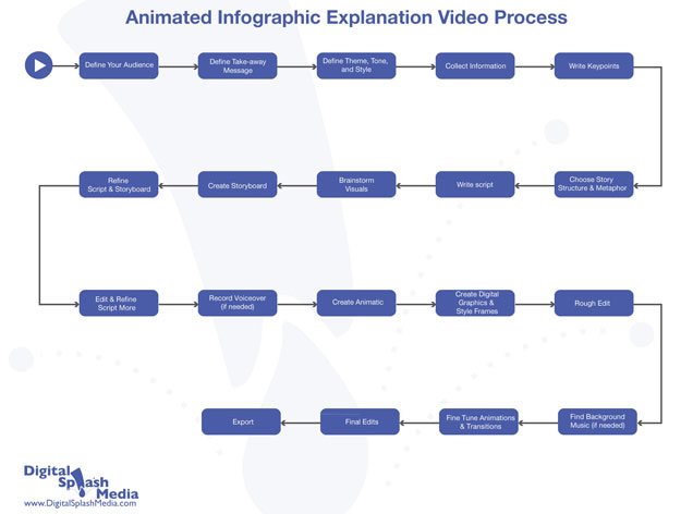
 Objective C focuses on the realization or creation of a solution to a problem.
One of the most difficult aspects of design is to take an idea from paper and create a product that someone can interact with: a solution to a problem. 

In objective B, you developed planning drawings and/or diagrams to clearly depict what you are making. In this first strand of objective C, you detail how they will make your solution.

By constructing a logical plan that details the steps required to make a solution, you will demonstrate your knowledge and understanding about how solutions can be made.

What are resources?

Resources can be categorized in two ways: materials and tools.
It is simple to identify tangible materials such as hardwood or nylon; however, it can become more problematic to determine digital materials. 

- When identifying digital materials, you should consider text, fonts, images, audio, video, animation, sprites and icons.

- For digital design, tools include both software and hardware (input, processing and output devices). 

For product design, tools include: hand tools, machinery, CAD (Computer Aided Design) software, EDA Electronic Design Automation software (EDA) (e.g. Fritzing) and CAM hardware (e.g. Fritzing Fab).

Quality control and assurance

Quality assurance covers all materials from design to documentation. It includes the regulation of quality of raw materials, assemblies, products and components, services related to production and management, and inspection processes.
Quality control manifests itself in the development checking and testing of systems to ensure that products or services are designed and made to meet or exceed specifications.


Examples of plans

Step-by-step plan
 Step Process (including quality control, health and safety considerations) Tools Materials Time to complete
 1
 2
                                                                  Step-by-step plan template

                                                                                                  Step-by-step plan example
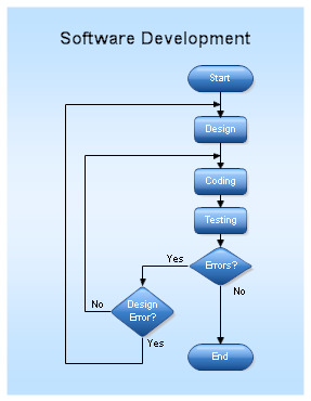
Gantt chart/slippage chart
Gantt chart is a project-management tool used to provide an overview of a process. A Gantt chart divides the manufacture of a product into small tasks. It indicates the time estimated for each of these tasks and theresources required. It does not provide a detailed set of instructions, but instead is an overview to self-assess progress with a project. You should indicate when each task is complete.

Gantt chart example

slippage chart goes one step further than the Gantt chart in that it has room below each task to mark when it was completed (in green), allowing you to identify when they are behind in their plans and take action to get back on schedule.

Slippage chart example

The following questions can help you consider your planning.

  • Does your plan contain a sequence of logical steps?
  • Is the use of resources explained clearly?
  • Have you made sure you have enough time to complete your product?
  • Have you given time for practising or learning a new skill?
  • Have you allowed extra time in case something goes wrong?
  • Have you considered alternative ways of creating the solution?
  • Have you planned for testing at appropriate times in the manufacturing process?


    (ii) Demonstrate excellent technical skill when making the solution

    At the end of year 5 you should be able to:


    • develop manipulative skills to effectively use a wide range of tools, techniques and equipment
    • use a wide range of tools and equipment proficiently to create high-quality solutions
    • ensure a safe working environment for themselves and others

    To determine the correct level of technical skill which you are operating at, teachers need to consider the complexity of skill demonstrated as well as the level of guidance that is needed to provide in order for you to complete the task.
    When determining the complexity of skill demonstrated by you, a number of indicators will be considered.

    • Accuracy of the solution: Have all parts been made as detailed in the plan? Have all parts been made accurately?
    • Final aesthetic quality of the solution: Has the student given appropriate attention to detail, considering the final overall look and feel of the solution?
    • Assembly of the solution: Do all components fit together or combine as detailed in the plan?
    When determining the level of guidance and support needed, teachers will consider that you:

    • can be given initial guidance and demonstrations by the teacher
    • can practise the processes as required
    • must work independently when making the solution, if they are to achieve the higher levels
    • should demonstrate safe working practices.
    For digital design, the level of technical skill demonstrated can be shown through the functionality of the assembled solution. For product design, the level of technical skill demonstrated can usually be shown through the functionality and the final finish of the assembled solution.


    (iii) Follow the plan to create the solution, which functions as intendedBy the end of year 5 you should be able to:


    • independently follow the plan to produce the solution, which functions as intended
    • manage time effectively to produce the solution to the deadline stated in the plan

    You will demonstrate that the planning process was sufficiently thorough if the final product matches the planning drawing and no changes were made to the plan, in whatever form it was presented. If the drawings/diagrams and the plan match what has been made, then you have followed the plan.
    If a you do not follow the plan, it will usually result in the solution not fully meeting the specification and/or matching the design detailed in the drawings/diagrams.

    (iv) Fully justify changes made to the chosen design and plan when making the solution

    By the end of year 5 you should be able to:


    • justify, through the use of drawings/diagrams, any changes made to the design while making the solution and how they affected the plan

    As you implement your plans, you will often come to a point where you will have to modify the plan or the design. You will need to ensure that you detail and justify any changes that you make during the creation process.
    If you do not make any changes to your product or plan, this strand does not have to be addressed with evidence. However, if any changes are made, you must address this strand.
    There are two main changes and modifications I have made to my original idea:

    1. The hole on the edge of the small wooden pieces (used for the numbers) used to help lift the pieces was originally a square of dimensions 15mm x15mm. Nevertheless, I have found a better solution that is easier to create and is more practical. I will instead create a circle of radius 10mm. This will be done using a bench drill which is easier and faster than cutting it in a square shape using a saw, especially since I will be creating 20 pieces of these.
    2. In the original plan, the snake was supposed to be painted on the top 600 x 420mm wooden piece, with the holes for the number pieces being in it. Nevertheless, I have found a better solution which is to cut out the snake (with the dimensions listed in the ‘Parts list’ page) and create the holes in the snake itself. This would not only make the product more attractive, it would additionally make its creation more practical and easier since it would be easier to rotate the snake than the whole board when creating the holes.
    Changes made to design example: Educational toy
    On the home page…
    The link has moved from the very bottom to almost near the top, I had done this for aesthetical reasons. The quote, instead of having it centered, it is now flushed right, this was because I needed to create more of a visual balance. Other than that, it appears the same in the design as it does in the final product.
     Design Solution


                                                                      Changes made to design example: Website
    MYPdesign43
    Changes made to design example: Making a box
    Modification to my Design
    Now that I have made a plan to follow and thought about all the materials, tools I am going to use and how much time the project is going to take, some features of my design changed.

    1. To start with, I changed the thickness of the circle of the sun which is where I am going to locate the clock mechanism. This is because the part of the clock mechanism that has to be drilled through the material is 6cm long. So, it is going to take a long time to drill a whole about 14cm deep on an 18cm thick material. I thought it would take less time drilling a whole about 2 cm deep on an 8cm thick material
    2. Now that I thought about how long it is going to take to create stickers, I decided make more Number Stickers. Before I made the plan, I thought it would take the longest time to create the stickers on the vinyl cutter; however, I realized it actually doesn’t. I was going to only make four stickers: 12, 3, 6 and 9. But, since it doesn’t take so much time creating them, I decided to make all twelve stickers. I also realized that while I am waiting for the stickers to be cut out by the vinyl cutter, I could be using the time and start working on the next step which is putting the clock mechanism on to the clock design.
    3. The last change I have made is to use spray paint for one or two parts. If I use paint, I have to paint several coats and dry them. Same goes for spray paint; however, if you compare the time on how long it takes to paint and spray a material once, to spray paint takes less time.
                                                                                             Modifications to a design example


    (iv)(a) Present the solution as a whole

    At the end of year 5 you should be able to:
    • present the solution in an appropriate format that shows all details of construction

    A digital design product will be presented as either an executable file or readable file.
    A product design outcome will be presented as a set of photographic images, which must show detail and scale.


    Read
    MYPdesign46Presentation of website solution example
    MYPdesign47Presentation of a product from all angles example: Key ring
    MYPdesign48

    Criterion B: Developing Ideas. (additional info)

    Developing Ideas


    (i) Develop design specifications, which clearly states the success criteria for the design of a solution.

    By the end of year 5 students should be able to:


    • identify and explain the requirements of the solution based on the analysis of the data and identify which are essential and which are desired


    i) What is a design specification?specification is a set of constraints, requirements and considerations for a solution: what the solution must or must not have to be successful.

     A specification is not a description of the outcome. It should demonstrate that you understand the needs of the problem that you have identified. Every aspect of a specification must be specific, measurable, achievable, realistic and testable (SMART).

    The specification should be directly connected to your design brief. Writing a specification can be a difficult job if the design brief is not well researched and written. If a solution or design fails to meet an aspect of the specification, it can be considered that it has not met the criteria for success.

    You will need to refer back to your specification throughout the project, particularly when developing ideas and evaluating the solution.


    The table below demonstrates poor and good examples of design specifications. Remember that these should be specific, measurable, achievable, realistic and testable.
     Poor examples of a design specification Good examples of a design specification
    My storage device must look good/nice.

    The interface must look attractive
    The storage device must contrast with the furnishings of the room; so bright colours such as red, yellow and orange would work really well.The interface must appeal to my target audience; whose favourite colours are hot pink and deep purple.
     It must work well.

    It must function correctly.
    The clock must display the time accurately.The clock must have a method to hang it on the wall.The storage device must store my jewellery collection (list the specific types of jewellery and quantity) 10 rings, 5 bracelets and 10 pendants.

    All information on the web page must be accessible using 3 clicks or less. 
    My storage device must be the right size.My storage device must be able to hold 20 pencils that are 170mm long and 8mm in diameter.The images on the web page must be clear and visible when viewing from 50cm from the screen.
     My animation should be fun.My Flash animation should contain animated graphics that carry the meaning of the song included, sing-along with bouncing dots and appropriate typography (Sassoon Primary or similar.)
     My video must include music.My video must include up-beat, hip-hop style music.
     My video must not be too long.My video must be last at least 1 minute and no more than 2 minutes.


    Changing specifications during a unit of work

    You may have opportunities to develop your specification further as you continue through the unit of work.Changes in a specification should be justified through additional research that you may need to conduct as a result of finding that an aspect of a specification is not appropriate.


    ii) Develop a range of feasible design ideas that can be correctly interpreted by others

    By the end of year 5 students should be able to:

    • develop and use a wide variety of techniques to generate a wide range of distinctly different designs through 2D and 3D modelling that are easily interpreted by others
    • annotate designs with sufficient detail to explain how they meet the requirements of the design specification and to explain design thinking
    • evaluate designs against the specification to identify the most feasible solutions
    • develop the most feasible solutions to create a final design through modelling that fully meets the requirements of the design specification

    For both digital and product design, a natural starting place when designing is with a pencil and sheet of paper, developing rough sketches of potential solutions. 
    You should focus on getting the basic building blocks of ideas sketched out in short, concentrated bursts. 

    These initial ideas should focus on generating a range of different solutions to the problem.
    You should then identify which initial ideas should be developed further. This could be done through a range of strategies, including:

    • further, more detailed sketches that start to develop ideas with direct reference to the specification
    • detailed annotation that allows students to explore and communicate their own thinking through annotation
    • making of simple card and CAD models and simulations used to test ideas and ensure they meet the specification.


    Design idea development examples
    MYPdesign6Initial sketched idea example: Animated website


    The table below describes examples of strategies and techniques to communicate and develop ideas
     Technique/strategy Digital design Product design

     Initial concept sketching
    • Layout drawing
    • Storyboard
    • Scripts for audio
    • Two-dimensional sketches
    • Three-dimensional sketches including perspective; crating; oblique, isometric and projection
    • Rendering to show form, colour and texture

     Development drawings

    • Detailed layout page design
    • Visual mock-ups
    • Web trees/maps
    • Detailed audio script including directions on pitch, sounds, pause lengths, pace and music

    • Orthographic projection to scale
    • Sectional views
    • Exploded drawings
    • Part and assembly drawings

      Modelling

    • Mock-ups
    • Prototypes
    • Simulations

    • Card models
    • Prototypes
    • Three-dimensional CAD models
    Communicating and developing ideas

    What does it mean to develop an idea? How do I present this information?

    Designers do not come up with a single, static idea that solves all aspects of a problem; designs are developed over time in an iterative fashion. You should record your iterative development through design sketching, modelling, refining and testing. This is all part of design development.

    range is not quantifiable. The number of ideas you create depends on the complexity of the problem, age, level of experience and time. When students ask how many ideas they should generate, the simple answer is: as many as it takes to solve the problem and to develop a design that meets all of the design specifications.

    When developing your design ideas, you must always be working towards the goal of designing a solution to the problem, for which the requirements have been defined through the design specification. 

    Therefore, you must work towards developing at least one design to meet the specification.
    You should develop, or refine, every detail, including:

    • the exact size and shape of individual components
    • the required and/or available materials
    • how the components fit together to create the whole
    • the required and/or available tools and equipment
    • aesthetics (colour, texture, shape, form, line, balance, finish)
    • how the user will interact with the solution
    • aspects relating to safety and accessibility.

    What is a feasible idea?

    feasible idea is an idea you could successfully make independently in the given time, with your skills, and with the resources at your disposal.
    You can include ideas in your design folio that do not achieve all specifications successfully, but these ideas should lead to feasible ideas through design development or be constructively criticized through annotation to highlight weaknesses and suggest improvements.
    To ensure that ideas are feasible, they may need to be tested using mock-ups or models.

    The following questions may help you reflect on your design ideas.
    • Do I need to do more research to complete my design? For example, how do I join one part of my design to another?
    • Does the school have the resources (tools, machinery, hardware, software or materials) to make the design?
    • Do I have the skills to make this design? Can I gain the skills to make this design?
    • Will I have to get any resources myself? If so, where and when?
    • Will I be able to make this design in the time available?

    Why is "annotation" important?

    Annotation is vital for you to communicate the thinking behind your ideas and how that thinking develops. This is why annotation is so important. Simply sketching ideas will not clearly communicate them, as other people looking at these ideas may not interpret them correctly. 

    Think about the following questions when writing your annotation.
    • How did you come up with the idea? Did something influence your thinking?
    • What materials do you think should be used, and why? Are the materials available?
    • How could the idea be made? What tools, equipment and processes would you use?
    • Could the design be made in the time available and with your skills?
    • Would it cost too much?
    • Is it safe?
    • Do you think your client would like the idea?
    • Why did you choose this colour/texture?
    Other elements you should incorporate into your annotation include: how one idea led to another; how you could improve/develop your design ideas; whether you need to do more research, for example, into materials; and whether the client thinks your ideas are suitable.

    Do all ideas need to be evaluated against the specification?

    When designing, you need to develop your ideas towards meeting the design specification, resulting in your final design meeting the criteria. You should constantly consider the design specifications as you design and reflect this in your annotation. An evaluation of the final design against the specification should be included as part of the design’s selection.


    Correct interpretation of design ideas

    The correct interpretation of design ideas is vital for clear communication of ideas between a designer, client, target audience and manufacturer.
    You are assessed on the quality of your design communication through strand 2, encompassing your sketching, modelling, refinement, development, testing and annotation of designs. If the teacher cannot determine or interpret the design, it is not sufficiently represented and the design thinking has not been clearly articulated.
    You will need to combine your design sketching, mock-ups and models, CAD and annotation to clearly articulate your ideas.


    iii) Present the final chosen design and justify its selection


    By the end of year 5 students should be able to:

    • present the chosen design in an appropriate format including detailed annotation that justifies the choice of design by referencing the requirements of the design specification


    Selecting and justifying the chosen design

    When working with a client or target market, feedback is a vital source for selecting a design to take forward for prototyping. You should formulate questions, which could be delivered in the form of an interview or survey, to find out which design your client likes the best and why. You could then summarize findings in a written statement.

    The questions should focus on gaining feedback related to the aspects of the specification that have qualitative/subjective parameters. You should recognize that clients may change their minds at this point, and therefore the specification: you may have to redevelop your chosen idea.

    You will also need to critically evaluate the chosen idea against each specification and justify how the chosen design satisfies the specification. If the design does not meet the design specification, it needs further development—or the specification needs redevelopment


    Example 1
    In figure 34, the student can choose to disregard design C, which meets the design specifications, and continue to develop designs B and D. Design D is developed further to meet the design specifications fully. However, design B needs much more development to meet the design specifications.
    MYPdesign26Figure 34-Selecting and justifying the chosen solution

    If the teacher informs the student that design D cannot be made due to the unavailability of a resource, the student can then either develop design B further to incorporate the required change or change the design specification so that the existing design can meet it.


    Example 2
    In figure 35, the student assigns a quantitative rating of how well each design meets each of the design specifications. Design 2 seemed more likely to be chosen because it received the highest rating from peers. However, feedback from the client indicated that the design was not preferable.

    Designs can be further developed to improve their weak ratings against particular specifications, but when designs are developed for a particular client as opposed to a target audience, after the design has been developed to fully meet the design specifications, the client has the final choice.


     Design specifications Incorporation of the theatre mask image Use of colour Simplicity of design Overall presentation
     Logo
     Total score
     Design 1 1 3 3 1 1 9
     Design 2 4 4 1 4 4 17
     Design 3 2 1 2 2 0 7

                                                         Evaluation of designs against specifications: Feedback from peers
            The results from the table above show that design 2 received the highest overall rating (17/20) and therefore should be refined further and chosen. 


     Meets design specification Ranking
     Excellent 4
     Good 3
     Slightly 2
     Not at all 1

    Presenting the chosen design


    When presenting the final chosen design, you must provide a clear image of that design, which clearly shows its details and features. This image should be presented as a final illustration, separate to any developmental work.

    For product design (grade 10), students create a clear, well-presented illustration of the final chosen design that highlights details such as colour, form, texture, proportion, how the solution functions and all its features.

    For digital design (grade 9), students create a clear, well-presented illustration of the final chosen design that highlights details such as colour, form, fonts, layout, how the solution is interacted with and its features.
    MYPdesign19Figure 29-Final design presentation example: TV advertisement


    Figure 30-Final design presentation example: Drawing


    Figure 31-Final chosen idea examples (showing development)

    By the end of year 5 students should be able to: 


    • develop a series of accurate drawings/diagrams that include sufficient details of the design for peers/others to interpret correctly to make the solution

    • include details of size, assembly and production methods in their drawings/diagrams

    Why do I need a planning drawing/diagram?


    Typically, designers will develop their ideas and create detailed drawings/diagrams for a manufacturer to create a final prototype/sample/model. 

    To get the correct solution created to the correct specification, designers must communicate their final chosen solution to a manufacturer very clearly. Planning diagrams and drawings are communication tools that are essential for good design.

    When designing solutions to problems, you need to ensure that you have a very clear idea of what you will create. 

    There is often a great difference between the “idea” and the “realized solution”. To ensure that the idea and realized solution are the same, you should consider all aspects of creating the product. Through the development of design ideas, you should have identified:

    • which materials will be required (digital or tangible, standard or customized components, and so on)
    • which tools and processes will be used (hardware, software, techniques and so on)
    • the size, tolerances, position (layout) and assembly of components
    • the overall visual appearance.

    These elements must be defined clearly through planning drawings or diagrams that are sufficient for someone else to follow.

    In Digital design, three key items are usable;


    A. Table of requirements based on design specs/ .

    Step
    Task
    Requirement/ Description
    Resources/materials
    1.
    Signup to Wix   

    •        -  Signup an account on www.wix.com
    •        - Remember user name and password.
    •        - Choose the domain name: www.victorwamurwa.wix.com
    •      - Type the Title of the website; 
    My Culture My Choice.
    -internet
    - Wix web builder
    - computer
    2.
    Login to Wix          account

    • -          Use the username and password to login.
    • -          Scroll through the templates and layouts.
    • -          Select a layout with Blue and Yellow colors
    - internet
    - Wix web builder
    - computer


    B. Flowchart Symbols

    checkout the following link for more on flow chart. http://www.smartdraw.com/flowchart/.of interest when interacting with the site above is the a) flowchart examples and b) flowchart symbols.

    Take a case example of someone developing a database to:

    i) capture records of books in the library

    ii) register library users

    iii) handle borrowing and returning of books


    .


                                          Sample flowcharts.

    1. website        flowchart


                                Animation / Video


    Games


    Apps/ CookBook


    Magazine


    C. Sitemap/ Layout                                                              

    Sitemaps on the other hand explain the layout of your project. It would explain the various tables and the interconnection among the tables in the case of a database. 


    It explains the various pages and how they are linked in the case of a website, and so is the case for any other application.


    Take a case example of the following website:
    http://www.beachcampwatamu.com/


    1. Magazines


    2. Website


    3. Apps


    4. Games


    5. Magazines


    6. Video/ Animation


    What modes and media are appropriate for planning drawings/diagrams?
     Digital design Product design

    • Details of components (identification, size/scale, colour, fonts, etc)
    • Screenshots demonstrating visual layout
    • Storyboards
    • Web trees and details of identified components (text, images, fonts, audio, video, sprites) to be used
    • Layouts/templates designed by the student
    • Interface layouts
    • Detailed sketches (graphic design models)

    • Details of components (identification of standard components, size/scale, material, finish, etc)
    • Sectional and exploded views
    • Orthographic projections/working drawings (conventions/standards, scale, units of measurement) and a cutting list
    • Circuit diagrams/printed circuit board layout
    • CAD (Fritzing)/freehand/instrumental
    • Nets/developments and patterns
                                            
                                             Table 24-Appropriate modes and media for planning drawings/diagrams


                                                             Assembly drawing example: chair

    Parts list – Jewellery Box
    Part:Material:Dimensions (mm):Quantity:Tools:
    SidesPine wood120 x 80 x 122Tenon saw
    Front & BackPine wood180 x 80 x 122Tenon saw
    Base & LidPine wood120 x 180 x 122Tenon saw
    FabricBlue felt.5 Square1Scissors & glue
    HingesBrass322Battery drill and Screw driver
    NailsSteel22 long8Hammer & Nail punch
    Timber stain & Varnish---Cloth & Paint brush
    Lock & KeyBrass-1Battery drill, File & Screw driver
    HandlesBrass-2Battery drill, File & Screw driver